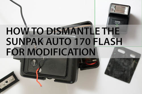
I picked up a Sunpak Auto 170 flash / speedlight from eBay for a few quid recently. I bought it with the intent of removing the light sensor that it uses to calculate the power needed in auto mode, and replace the sensor with a potentiometer. This allows manual control of the flash - you can find plenty of tutorials on the web about doing this with any 'auto' flash.
The issue I had when I received the flash unit was how to get it open - there are no screws! Eventually I did manage to open it, though not without considerable struggle and damaging the seal between the front and back sections of the case. So, to help anyone else who might want to modify this flash, I thought I'd post the correct way to dismantle the flash. I suspect that the Sunpak 20SR flash also uses the same case design as the 170, so if you're looking to dismantle a 20SR, this guide may be useful too.
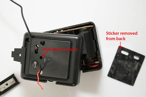
The key to opening the flash up is that there is actually a single screw holding the two halves of the case together. This screw is located underneath the flash power guide table on the back of the flash. Slide the blade of a knife under the sticker and gradually work it loose (it is stuck down quite well).
When the sticker is removed it will reveal a hole in between but slightly further up than the power switch and power light. There is a deeply recessed screw inside this hole. You need a phillips head screwdriver with a thin shaft to get into the hole and down to the screw.

Note that the two wires coming through the hole on the back of the flash are just there because this photo was taken after I modified the flash. I wanted the wires (previously attached to the light sensor) running outside the case so that the potentiometer can be attached on the back of the case.
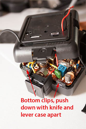
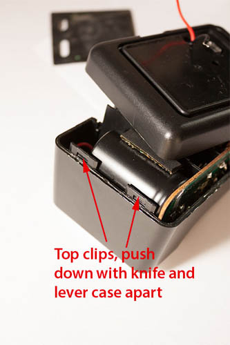
Once the screw has been removed you can start to separate the case halves. There are four clips holding the two halves together, two at the top and two at the bottom. Use a knife to push down on each clip and push the halves away from each other, one clip at a time.
When the case halves are separated at all four clips, then you should be able to pull the halves apart. Be careful with the power light cover, which is loose on the outside of the back half of the case when the sticker has been removed. And also be careful with the red test switch, which is loose on the inside of the back half of the case. You don't really want to loose any parts.
Job done!
If you want to access the light sensor, use the blade of a knife to lever up the bottom circuit board. Then use your knife to lever the light sensor out of its fitting in the case (this is quite fiddly since the bottom circuit board is still partly in your way).
When putting the flash back together, I found that I had to put the case halves together at the top first, and then at the bottom. But this could be because I might have damaged the top in my efforts to open it when I didn't realise there was a hidden screw keeping the two halves together. Make sure that the battery compartment is in place and aligned correctly before you snap the two halves back together too.
I haven't finished modifying my flash yet as the 100K potentiometer I tried it with only started having any effect when it was turned about half way down. I've now ordered a 50K one, so I'll see how that goes.
I also noticed that with the potentiometer turned to give minimum flash power, one of the components in the flash would spark and there would an audible 'click' noise when the flash fired. Likely the light sensor has a minimum resistance that is higher than the minimum resistance on my pot, and the flash is not designed to work with a lower resistance than that.


Interesting project, but as of 2023 the used market such as Ebay is flooded with flash units from the film era that are almost being given away. For a few quid you could probably get one with variable manual and auto modes already, such as a Sunpak 26DX. That Auto 170 probably has a high trigger voltage that could fry a digital camera’s electronics.